
News
DIRECT ANSWER: Bubbles in a GOB coating are usually process air, not bad glue. Air gets in at four places: in the mixed glue, in the feed and dispensing path, at the module surface, and during cure. Find which of the four by where the bubbles sit and when they appear — the diagnostic table in section 3 does exactly that. The material datasheet gives the two hard rules for the glue JHIMS supplies: potting below 20 mm self-defoams, thicker potting needs vacuum defoaming for at least 5 minutes at 700 mmHg, and heating to speed the cure is not recommended because it causes pinholes and bubbles. Fix the entry point, prove it on a trial module, and only then run the batch.
A coated module comes off the line looking right — until the light catches it. Small round voids under the surface, pinholes breaking the top, a line of bubbles along one edge. The coating is supposed to protect the module. Instead it has locked a defect inside, where no cleaning step can reach it.
The first instinct is to blame the glue. Most of the time that is the wrong place to look. Suppliers degas two-component materials before they ship them, and a batch that mixed cleanly last week does not suddenly become full of air on its own. Air enters during handling, mixing, dispensing, or cure — which means it can be found and stopped. This guide works through the four entry points, shows how to read the bubble pattern to find the one that applies to your line, and sets out the defoam decision and the line changes that stop bubbles at the source.
This guide is about bubbles that appear during coating and cure. Deciding whether a coated module with bubbles can be reworked or must be scrapped is a separate decision, covered in our guide to reworking a GOB-coated module. What counts as an acceptable number of bubbles is a matter for your own acceptance limits — this guide gives you no numbers for that, because no JHIMS test data exists to set them.
Not everything round in a coating is the same defect, and the fix depends on which one you have. Three forms matter on a GOB line.
Why it matters is straightforward. A void under the coating is a weak point in the seal and a visible defect in a display module. A pinhole is an open path for moisture and dust. A blister is a coating that has already failed locally. None of these is fixed by coating over the top — a second layer traps the same air underneath. That is why the work in this guide happens before and during coating, not after it.
One more distinction before the causes. A bubble that appears on every module in a batch points at the process — the glue, the machine, or the room. A bubble that appears on one module in a batch points at that module — its surface, its history, or the way it was handled. Keep that split in mind while reading the diagnostic table in section 3.
Air does not appear from nowhere. It enters at one of four stages, and each stage leaves a different signature. Work through them in order, from the glue drum to the cured coating.
| Entry point | How air gets in | What it looks like later |
|---|---|---|
| 1. Mixing | Hand stirring folds air into the mix; a fast stir whips it in. Air trapped between the fluid surface and a piston, or introduced when a container is refilled, travels with the glue to the valve. | Bubbles spread through the whole batch, often small and evenly distributed. |
| 2. Feed and dispensing path | Air in the lines, a loose fitting, a half-empty tank, or air dissolved in the glue under feed pressure. A valve that drips or sucks back between shots pulls air into the next shot. | Bubbles that come and go — worse after a stop, worse at the start of a run, better once the line is flowing. |
| 3. Module surface | Dust, moisture, or a surface the glue does not wet well traps air under the advancing glue front, especially around tall components and along edges. | Bubbles clustered at edges, around components, or on one module only. |
| 4. Cure | Heat applied to speed the cure, or gas released as the glue cures, expands small bubbles that were invisible when the glue was laid down. A skin forming early seals gas underneath. | Pinholes and blisters that were not there at coating, appearing as the coating sets. |
Mixing. Two-component GOB glue is mixed before it reaches the machine. The OPT315 silicone supplied by JHIMS is mixed at a weight ratio of A:B = 10:1, and the page instructs component A to be stirred before mixing and component B to be shaken well in its sealed container. Stirring is necessary — but stirring fast is not. Vigorous hand mixing folds air into the material, and once air is in a viscous mix it does not rise out on its own. Machine mixing avoids this: the JH-G810 fills LED modules with two metering pumps that dose each component in the set weight ratio, a blending device that mixes them evenly, and an AB back-suction valve. The metering pumps are the point — a fixed ratio delivered by pumps does not depend on how hard somebody stirred.
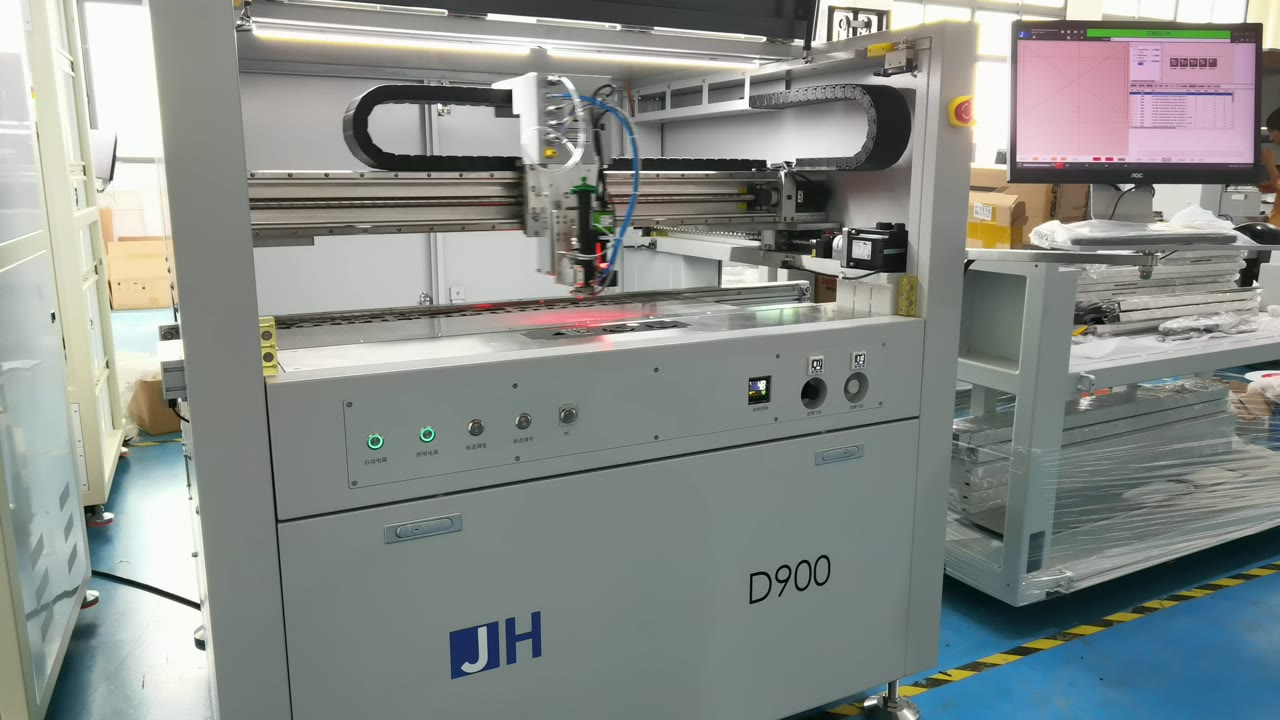
The JH-D900 precision jet dispensing machine — shown here as a dispensing reference, not a GOB coating machine. The gantry carries the dispensing head over the work area while the program runs on the monitor. The dispensing step is the second place air gets in, so the state of the feed path and the valve matters as much as the state of the glue. Frame from JHIMS's own D900 dispensing video.
Feed and dispensing path. Between the mixed glue and the module there is a path — tank, lines, pump, valve, nozzle — and every joint in it is a place air can enter. A tank run low lets the feed draw air. A fitting that weeps lets air in between runs. A valve that does not shut cleanly drips, and a valve that sucks back pulls air into the nozzle. Pressurised feed systems can also hold air dissolved in the glue, which comes out as bubbles when the pressure drops at the nozzle. This is why the machine-side features exist: the GOB-LXS330 carries an anti-drip valve that prevents glue overflow and dripping, and a liquid level sensing alarm that warns when the glue level needs attention. As a precision reference, the JH-D900 runs a purge cycle at startup, cleans its jet valves with a self-cleaning vacuum system, and checks each shot against a weight control accurate to ±0.005 mg — a drift in shot weight is often the first sign that air has got into the path.
Module surface. Air can also be trapped by the module itself. If the surface is dusty, damp, or contaminated, the glue does not wet it evenly; the advancing glue front bridges over a low spot or a component edge and seals a pocket of air underneath. This is the one entry point that is about the module, not the glue or the machine — which is why it usually shows on some modules and not others. Checking the bare module before coating, and confirming the surface is clean and dry, is covered in our guide to inspecting the bare LED module before coating.
Cure. The last entry point is the one most often missed, because the bubbles are not there when the module leaves the machine. The OPT315 page states it plainly: heating to cure is generally not recommended, because it can cause pinholes or bubbles on the surface and inside, and affect the appearance and the sealing performance. Heat makes small trapped bubbles expand, and it can skin the surface over while gas is still escaping from below. The same page notes that this silicone cures at room temperature and releases ethanol molecules as it cures — gas that has to get out. A coating that is rushed through cure gives that gas nowhere to go.
Before changing anything, look at where the bubbles are and when they appeared. The pattern is the cheapest diagnostic tool on the line. The table below is a diagnostic heuristic built from the evidence in this guide — use it to choose the first check, then confirm on a trial module. It is not a guarantee: two causes can produce the same pattern, and only a trial separates them.
| What you see | Most likely entry point | Check first |
|---|---|---|
| Small bubbles evenly spread through every module in the batch | Mixing — air folded in when the glue was mixed | How the glue was mixed; whether the mix was degassed (section 4) |
| Bubbles worse on the first modules after a stop, improving as the run continues | Feed and dispensing path — air drawn in while the line stood | Purge cycle and first-shot check; tank level; fittings |
| Bubbles only along edges or around tall components | Module surface — air trapped under the advancing glue front | Module cleanliness and dryness; glue path and flow direction |
| Bubbles on one module only, neighbours clean | That module — its surface or its history | That module's record: storage, handling, previous rework |
| Pinholes or blisters that were not there at coating, appearing as the coating sets | Cure — heat, or gas still escaping under a skinned surface | Cure conditions against the glue datasheet; no added heat |
| Bubbles appear together with soft or uncured spots | Mixing ratio — air in a cartridge or feed can throw off the ratio, and an off-ratio mix may not cure properly | Metering and ratio: check the mix, not just the bubbles |
Two cautions. First, the pattern tells you where to look first, not what the answer is. If the first check finds nothing, move to the next row — do not keep adjusting the same setting. Second, write down what you saw before you change anything: which modules, where on the module, when in the run. A bubble problem that is not recorded is a problem that comes back next month with no history to compare against.
Not every mixed glue needs to be degassed. Whether it does depends on the glue and on how thick the coating is. For the OPT315 silicone, the datasheet draws the line clearly: potting below 20 mm thick generally defoams on its own, with no separate defoaming step. If the potting is thicker, pinholes or air bubbles may appear on the surface and inside — so the mixture should be put into a vacuum container and defoamed for at least 5 minutes at 700 mmHg.
That is a rule for one glue. Do not carry its numbers to another glue. A different material has its own datasheet, its own viscosity, and its own defoam instruction — and the numbers are not interchangeable. What does carry across is the method: check the thickness, check the datasheet, and defoam before the glue reaches the machine, not after it is on the module.
General industry practice, not a JHIMS specification. Published guidance on potting and encapsulation describes vacuum degassing as the standard remedy when mixed material holds air: a starting point of about 25–29 inHg of vacuum applied for around two minutes, then checked, in a vessel five to six times the volume of the material so the expanding mix does not spill. Treat that as a starting point for a trial, not as a setting — the glue's own datasheet, where it gives one, always wins.
Two practical notes. First, low-viscosity material self-degases more easily than thick material, because bubbles rise faster through it; fillers in the glue slow that down and can hold micro-bubbles on their surfaces. Second, degassing is a step with a clock on it: mixed glue has a working life, and time spent degassing is time the clock is running. That is why the defoam decision belongs in the batch plan — before mixing, not after the first bubbled module.
And one rule that is not negotiable for this glue: do not heat the coating to make it cure faster. The OPT315 page warns against it for exactly this reason — pinholes and bubbles. If the cure is too slow for your schedule, that is a planning problem, not a temperature problem. The cure conditions come from the material datasheet, as our guide to curing, handling and storage after coating sets out.
Once the entry point is identified, the fix is usually a small change in routine, not a new machine. Work through this list in order and change one thing at a time, so the trial module can tell you whether the change worked.
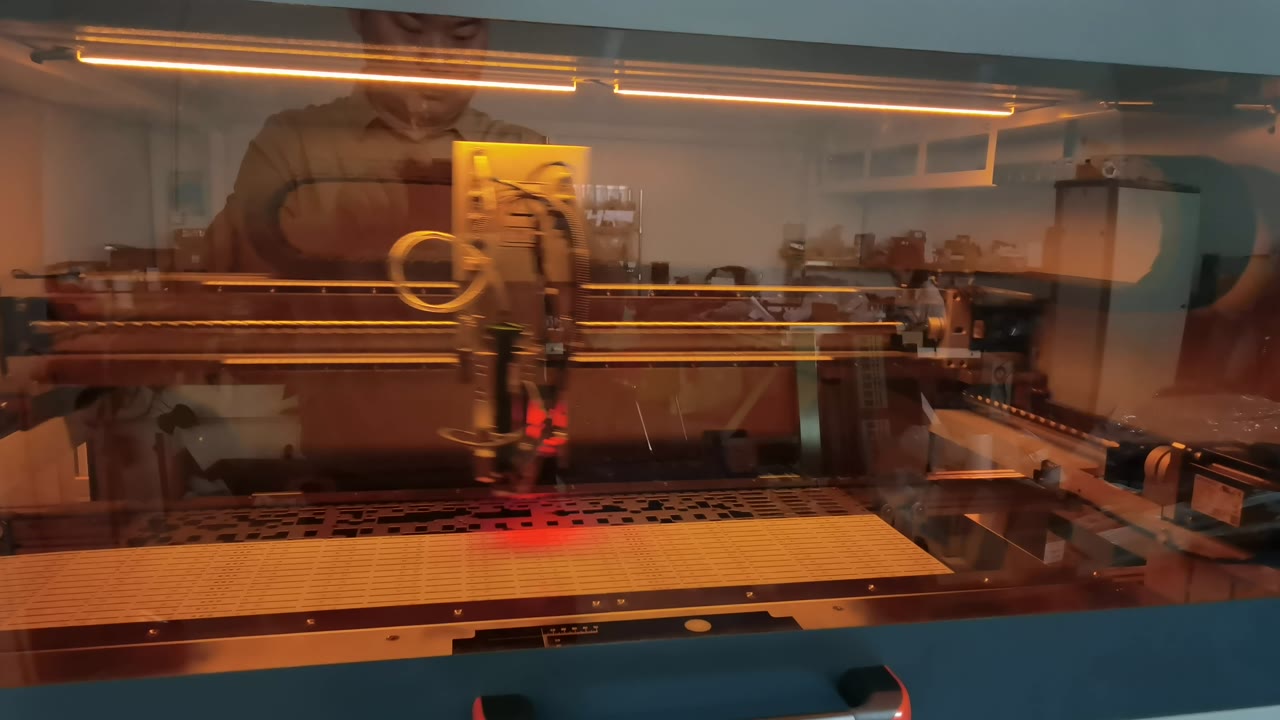
Close-up through the enclosure glass: the dispensing head at work over the work area, with the red dispensing point visible. The valve and the feed path behind it are where air drawn in during a stop shows up first — which is why the purge cycle and the first-shot check come before the batch, not after the first bubbled module. JH-D900 precision jet dispensing machine, shown as a dispensing reference, not a GOB coating machine. Frame from JHIMS's own D900 dispensing video.
Bubble prevention is mostly process discipline. The machines contribute in three places: keeping the mix right, keeping the path air-free, and telling you when something has drifted.
GOB-LXS330. The machine built as a GOB machine for LED displays and LED modules. Its contribution is on the dispensing side: a teaching program and parameter storage, so the same path and the same settings run every batch; an anti-drip valve, so glue does not ooze between shots; a liquid level sensing alarm, so a low tank is caught before the feed draws air; and a 0.5–0.8 MPa input pressure window, so the feed pressure is a set condition rather than a guess. Running accuracy is ±0.05 mm and the glue capacity is 30 L. One caution about the glue itself: the LXS330 page describes the coating material as a transparent epoxy resin, while the OPT315 page describes its own material as a condensation-type silicone. Do not pick a side between the pages. Follow each module's own production record and material datasheet for which glue it uses — the defoam and cure rules in this guide are quoted from the OPT315 datasheet and apply to that material.
JH-G810. The automatic glue filling machine for LED modules, for sealing and potting. Its contribution is on the mixing side: two metering pumps dose components A and B in the set weight ratio, a blending device mixes them evenly, and an AB back-suction valve controls the glue at the valve. Mixing ratio range is 100:100 to 100:10, dispensing precision is ±2%, and applicable glues include AB glue, silicone gel, epoxy resin, and PU. Vacuum pumping is listed as an optional configuration — the machine-side answer when the glue needs degassing support.
JH-D900 — precision reference, not a GOB machine. The D900 is a high-precision jet dispensing machine for semiconductor packaging, SMT underfill, and precision electronics assembly. It is included here because it shows what instrumented dispensing looks like: weight control accurate to ±0.005 mg that catches drift in shot weight, a self-cleaning valve with vacuum cleaning, and a maintenance schedule that names the checks — weekly nozzle and valve cleaning, monthly weighing calibration, quarterly full calibration and fitting leak checks. Borrow the discipline, not the numbers: a GOB line needs the same three habits — purge, weigh or measure the shot, and check the fittings — even if it measures them differently.
For the full machine context, the GOB LED display manufacturing solutions page sets out the line the LXS330 sits in. For the machines themselves, read the GOB-LXS330 product page and the JH-D900 product page — and compare like with like, since each page measures accuracy differently.
Stop the batch — and find the entry point before restarting — when any of these appears: bubbles on consecutive modules rather than one; bubbles together with soft or uncured spots, which points at the mix ratio rather than air alone; or bubbles that survive the defoam step and the purge, which means the cause is not in the glue or the path and the surface or the cure needs to be checked. Stopping is not lost production. It is the difference between a few trial modules and a batch of coated modules that all need a rework decision.
Before restarting, record four things: the glue lot and the mix time, the program name and the pressure reading, what the bubbles looked like and where they sat, and what was changed. That record is what makes the next occurrence a five-minute check instead of a fresh investigation. It is also what a customer audit will ask for — and the batch record is the same record our guide to handling GOB coating glue safely relies on for traceability.
Can I fix bubbles after the coating has cured?
No — not by coating over them. A cured bubble is sealed inside the layer. The module goes to the rework-or-scrap decision in our rework guide. Prevention before and during coating is the only fix that works.
Does a bubble always mean the module is scrap?
No. Whether a bubbled module can ship depends on your own acceptance limits — where the bubbles are, how many, and what the customer specification allows. This guide gives no acceptance numbers, because no JHIMS test data exists to set them. Decide against your documented limits, and record the decision.
Will changing to a different glue fix the bubbles?
Usually not. If the air is entering during mixing, in the feed path, at the surface, or during cure, a different glue meets the same process and bubbles the same way. Change the process first, prove it on a trial module, and only then ask whether the glue is the problem.
How do I know the defoam step worked?
Coat a trial module with the defoamed glue and inspect it before running the batch. A defoam step that is not verified on a trial module is an assumption, not a fix. If the trial module still bubbles, the air is entering somewhere else — work the diagnostic table again.
Do I need a vacuum chamber for every GOB job?
No. For OPT315, potting below 20 mm self-defoams and needs no separate step. Vacuum defoaming is for thicker potting, or when the glue's own datasheet calls for it. Check the thickness and the datasheet before buying equipment for a step you may not need.
Bottom line: Bubbles are a process signal, not a glue verdict. Find the entry point — mixing, feed path, surface, or cure — with the pattern in section 3, apply the fix in section 5, and prove it on a trial module before the batch runs. For OPT315, the datasheet's own rules are the baseline: below 20 mm it self-defoams, thicker needs at least 5 minutes of vacuum at 700 mmHg, and heat curing is not recommended.
For the GOB-LXS330 coating machine, the JH-G810 glue filling machine, or the OPT315 coating glue, contact JHIMS at [email protected]. Tell us the glue, the coating thickness, and where the bubbles sit — those three facts are what decide the first check.


 Teams
 whatsapp
 telegram
