
News
Short answer: Inspect the bare LED module before it is coated — not after. GOB coating seals whatever is on the module, including a dead LED, a weak solder joint, and contamination on a connector. A fault found before coating is an ordinary, accessible repair. The same fault found after coating is a coating-removal operation, a reseal, and a retest, with an appearance risk on top.
This guide gives that pre-coating check a fixed place in the line: a short sequence, a go / repair-first / hold decision for each module, and a record that lets a later fault be traced back to the module, not to the whole batch. It ends where coating starts. It does not set acceptance numbers — those must come from the module's own datasheet and the customer's acceptance standard, and this guide says so wherever a number would otherwise be tempting to invent.
On a bare module, everything a repair needs is still accessible. A dead LED can be seen, heated, replaced, and inspected directly. A suspect joint can be examined before it disappears under a continuous layer. A contaminated connector can be cleaned before anything seals the contamination in.
Once coating is applied, that access is gone. The coating covers the LEDs, the driver components, and the solder joints in one layer. Reaching any one of them means locally removing coating next to fragile, closely spaced LEDs, then resealing so that protection and appearance are both restored. A repair that works electrically but leaves a visible seam or a dull patch has still failed on a display product, because the finished screen is judged by eye.
That is the whole economic argument for a pre-coating gate, stated without any cost figure: the check itself is short, and it moves each fault to the point where fixing it is simplest. It does not eliminate post-coating inspection — coated modules still need their own acceptance check — but it stops the line from coating modules that were already rejectable.
Coating does not fix a defect. It preserves it, hides it from later optical checks, and makes it harder to prove what caused it. The table below lists the defects a pre-coating check is there to catch, in the order that matters for a display module.
| Defect on the bare module | What coating does to it | Why it cannot wait |
|---|---|---|
| Dead, dim, or wrong-colour LED | Seals the LED under a continuous layer; replacement then needs coating removal | Shows on the finished screen as a visible pixel fault |
| Missing, shifted, or damaged component | Locks the placement error in place | May pass a powered check at first and fail later, with no easy rework path |
| Suspect solder joint | Covers the joint so it can no longer be inspected optically | A joint that cannot be inspected cannot be cleared — it can only be guessed at |
| Contamination or damage on a connector or edge contact | Traps the contamination where the module connects to the cabinet | Connection faults found after installation look like cabinet faults, not module faults |
| Cracked board, bent edge, or a module that does not sit flat | Adds a rigid layer over a board that already does not sit flat | Shows later as a seam, a gap, or a flatness failure in the cabinet |
None of these rows needs a number to be useful. The decision they support is binary at this gate: the module is ready to coat, it needs repair first and then a second check, or it is held out of the batch. The numbers that decide borderline cases — how many dead pixels, what solder appearance is acceptable, how flat is flat enough — belong to the module datasheet and the customer's acceptance standard, and a general guide that printed its own numbers here would be inventing them.
Order matters. Checking the module in the wrong order wastes the earlier checks: a powered test on a module whose identity was never recorded cannot be traced, and a visual check after handling damage has already been done cannot tell when the damage happened. Run the sequence in this order, for each module, before it reaches the coating station.
Step 1 — Record the module first. Write the module identity, the batch it belongs to, and the coating material and program it is scheduled for, before any test result exists. A result without an identity is not evidence; it is an anecdote that cannot be tied to a module later. The record fields are listed in Section 6.
Step 2 — Visual check under controlled light. Inspect the LED face, the board surface, the edges, and the connectors under lighting that is good enough to see what a single overhead light hides. Shadows, glare, and a single viewing angle each hide a different class of fault: a shifted component hides in shadow, a solder defect hides in glare, a bent edge hides when viewed face-on. Look at the module from more than one angle, and do not treat "it looked fine under the bench light" as a completed check.
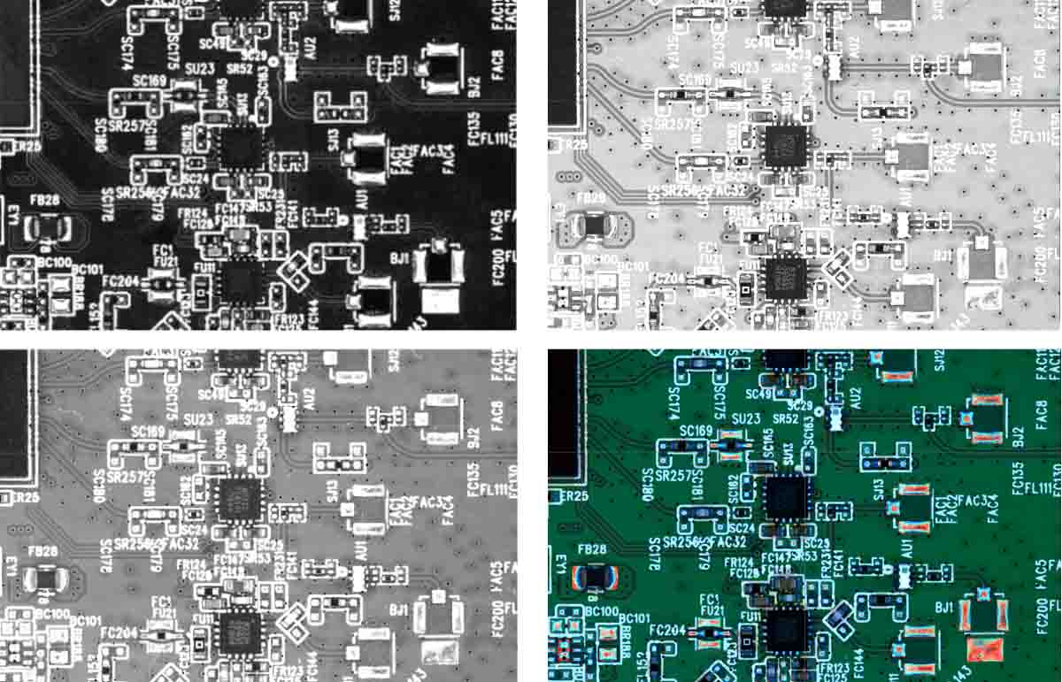
The same board area under four different lighting conditions. Lighting changes what an inspection can see, which is why a pre-coating visual check needs more than one light and more than one angle. This is an AOI lighting comparison image, not a photograph of a GOB module.
Step 3 — Powered functional check. Power the module on its test setup and check that every LED lights as expected, with no dead, dim, flickering, or wrong-colour pixels, and no row, column, or block out. This is the check that catches what a visual check cannot: an LED that looks perfect and does not work. The test pattern, voltage, and duration must come from the module's own test procedure — this guide deliberately does not invent them.
Step 4 — Connector and edge check. Inspect connectors, edge contacts, and mounting features for contamination, damage, bent pins, and anything that would prevent a clean connection or a flat fit in the cabinet. This check is about the module's interfaces, not its pixels: a module that lights perfectly on the bench and cannot connect reliably in the cabinet is still not ready to coat.
Step 5 — Flatness and handling check. Confirm the module sits flat on its fixture or tray without rocking or forcing, and that no handling damage has occurred since the earlier steps. A module that must be forced flat to be coated will not sit flat in the cabinet either, and coating over that problem does not correct it.
Only a module that passes all five steps goes to coating. A module that fails any step goes to the decision in Section 5 — it does not go to coating "to be dealt with later", because later means after the coating has sealed the fault in.
A failed powered check does not automatically condemn the module. The test setup itself — its power, its data connection, its fixture contact — can produce the same symptom as a module fault. Coating decisions made on a rig fault waste good modules and, worse, teach operators to distrust the check.
When a module fails the powered check, confirm the fault belongs to the module before dispositioning it. Swap the suspect module with a known-good module in the same test position, or move the suspect module to a known-good position. If the fault moves with the module, it belongs to the module. If it stays with the position, the cause is in the test setup, and the module must not be rejected on that evidence.
This swap logic will look familiar to readers of the companion guide on reworking coated modules, which uses the same logic after coating to separate a module fault from a cabinet fault. The method is the same; the question is different. Here the swap is done before coating, while the fault is still cheap to act on, and its purpose is to stop a good module from being rejected — or a bad module from being coated — on the evidence of a faulty test position.
Record the swap result with the module record. "Failed, then passed after swap" without saying which way the fault moved is not a record; it is a gap that will be argued over when the batch is questioned later.
Every module leaving this gate needs one of three dispositions, recorded by module — not by batch, and not verbally. A batch-level "mostly good" is not a disposition for any individual module in it.
| Disposition | When it applies | What happens next |
|---|---|---|
| Go to coating | All five steps pass, and the record is complete | Module proceeds to surface preparation and coating in the normal sequence |
| Repair first, then re-inspect | A confirmed, localised fault that is repairable on the bare module — for example, a single faulty LED or joint, with the cause isolated | Repair by the normal SMD repair procedure, then repeat the full five-step check; a repaired module that is not re-inspected is not cleared |
| Hold out of the batch | A widespread, unconfirmed, or unrepairable fault; a failed check whose cause is not yet isolated; or a missing record | Module is physically separated from the coating batch, labelled with the fault and the check that found it, and dispositioned separately — not coated to "see if it improves" |
Two rules keep this table honest. First, repair-first applies only to faults that are confirmed and localised. A whole row out, scattered faults across the module, or a fault whose cause is still unknown is not a repair-first case; it is a hold case, because local repair cannot fix a cause that has not been found. Second, a repaired module is not a passed module until it has been through the full check again. Repairing a pixel and skipping the re-inspection is how a repaired module ships with a second, unnoticed fault.
What this gate does not do is equally important. It does not decide whether a coated module can be repaired — that decision, with its five gates, belongs to the companion reworking guide. It does not set the coating program, the glue choice, or the surface preparation that follows — each of those has its own procedure. This gate has one job: no module reaches coating with a known, unrecorded, or unrepaired fault.
A pre-coating record exists for one reason: when a coated module is later questioned, the factory can answer whether that module was checked, what was found, and what was done — without relying on memory. Record these fields for each module, or for each defined batch where modules are genuinely indistinguishable by the customer's own traceability rule:
Keep the record with the batch, not in a separate file that no one opens when a fault appears. The companion guide on batch traceability makes the same point from the coated side: a batch record that cannot be found at the moment of a question is the same as no record. If the customer's traceability rule requires more fields, those fields govern; this list is a minimum, not a replacement for a customer requirement.
Coating a known defect to keep the line moving. The coating station being idle is not a reason to coat a held module. An idle station costs time; a coated defect costs a rework operation, a reseal, a retest, and possibly a module — and it can cost a cabinet position if the defect is only found after installation.
Inspecting only with power on. A powered check finds dead pixels. It does not find a bent edge, a damaged connector, or contamination that will matter at installation. The visual, connector, and flatness steps exist because the powered check cannot see them.
Inspecting under one light, from one angle. As the lighting comparison in Section 3 shows, the same board area presents differently under different lighting. A check done under a single light, from a single angle, is a partial check that reports itself as complete.
Skipping the record for "obviously good" modules. The modules that most need a record are the ones that passed without comment. When a passed batch is later questioned, "they all looked fine" cannot distinguish the module that was checked from the module that was never checked.
Treating the pre-coating check as a substitute for post-coating acceptance. Coating itself can introduce faults — coverage, edges, and cure all have their own checks after coating. Passing the pre-coating gate earns a module the right to be coated. It does not earn it shipment.
The gate matters because the coating step that follows it is precise, repeatable, and — once run — hard to undo. The GOB-LXS330 glue dispensing machine for LED displays is JHIMS's dedicated machine for this coating step. Its product page lists a running accuracy of ±0.05 mm, a 400 × 400 mm fixture, teaching programming, parameter storage for different products, a Panasonic PLC with touchscreen control, an anti-drip valve, and a liquid level sensing alarm, with a 30 L glue capacity and an input pressure range of 0.5–0.8 MPa.
Those specifications describe the coating step, not the inspection step, and they are cited here for one reason: a repeatable coating machine makes the pre-coating gate worth running. If coating varied from module to module, a pre-coating pass would not predict the coated result. With a repeatable application, a module that enters coating in good condition is at least starting from a known state — which is exactly what the post-coating checks then verify.
For the material side, the OPT315 potting and sealing material product page states a general mix ratio of A:B = 10:1, room-temperature curing, and that adhesion should be confirmed before use — with good adhesion to most electronic-part materials except PP and PE, and that heating to cure is generally not recommended. Those points reinforce the gate's logic from the material side: the coating chemistry must be confirmed for the module before coating, not discovered afterwards, and the material's own warnings must be on the record before the batch starts.
For precision context only — not a GOB machine — the JH-D900 precision dispensing machine lists a repeat accuracy of ±0.02 mm with a CCD vision system and a dispensing area of 860 × 400 mm. It is cited here only as a precision-dispensing reference for what controlled application looks like. Do not confuse the two machines: the GOB coating step in this guide is the GOB-LXS330, and the D900 is not a GOB machine.
JHIMS does not currently list a dedicated GOB machine page on its commercial site, so the GOB-LXS330 product page is the single source for this machine's specifications and should be read as such. Where this guide gives no number — acceptance thresholds, test patterns, solder criteria, flatness limits — that absence is deliberate: those values belong to the module datasheet and the customer's acceptance standard, and printing invented values would be worse than leaving the field for the reader to fill from their own documents.
Does a pre-coating check replace the first-sample trial coating?
No. The two gates answer different questions. Pre-coating inspection asks whether each individual module is fit to coat. A first-sample trial asks whether the coating result on a trial module is acceptable before the batch proceeds. A batch needs both: fit modules, and a proven coating result.
Does it replace post-coating acceptance?
No. Coating can introduce its own faults in coverage, edges, and cure. Pre-coating inspection prevents coating a module that was already faulty. Post-coating acceptance, covered in the companion guide on curing, handling and storage before the module moves on, verifies what coating itself produced.
What if a module fails only the connector check?
Hold it out of the coating batch. A module that lights perfectly and cannot connect reliably is not a good module with a small problem; it is a module whose field failure will be misdiagnosed as a cabinet fault. Repair or replace the interface first, re-inspect fully, and only then coat.
Can a repaired module go straight to coating?
No. A repaired module must repeat the full five-step check. The repair may have fixed the known fault and introduced another, and only a complete re-inspection can clear it.
What happens to a module whose fault is never confirmed?
It stays held, physically separated and labelled, until its cause is isolated or it is dispositioned as scrap under the factory's own rule. An unconfirmed fault coated "to see" becomes an unconfirmed fault sealed under coating, which is strictly worse.
Bottom line: Put the inspection where it is still cheap — before coating, module by module, in a fixed order, with a record. The companion guide on reworking a GOB-coated module shows what happens when that gate is missed: a second manufacturing operation to undo what coating sealed. A short check before coating is how that operation is avoided, one module at a time.
For technical information about the GOB coating equipment described here, contact JHIMS at [email protected].


 Teams
 whatsapp
 telegram
