
News
For SMT line managers and quality engineers who can add only one inspection station this year.
Direct answer: Neither station is the right first buy for every line. Buy SPI first when your escapes trace back to solder paste printing. Buy AOI first when your escapes are placement and post-reflow solder-joint defects while printing is stable. If you do not know which one dominates, run the four-step defect-origin audit in Section 2 before ordering anything — it takes your own rework log, not a vendor brochure, as the evidence.
SPI (solder paste inspection) sits immediately after the solder paste printer and before any component is placed. It measures the paste deposits themselves: volume, area, height, XY offset and shape, and it flags print defects such as missing paste, insufficient or excessive paste, offset deposits and bridging in the print.
AOI (automated optical inspection) sits after placement, usually after reflow, and sometimes at both points. It checks what SPI cannot see: missing or wrong components, polarity errors, tombstoning, lifted leads and post-reflow bridging and solder-joint appearance.
The distinction matters because each station is blind to the other station's defect class. SPI cannot tell you whether a component was placed correctly, because no component is on the board yet. AOI cannot tell you whether the paste volume under a component was correct, because the component now covers the deposit. Buying one station to fix the other station's defects is the most common inspection purchase mistake.
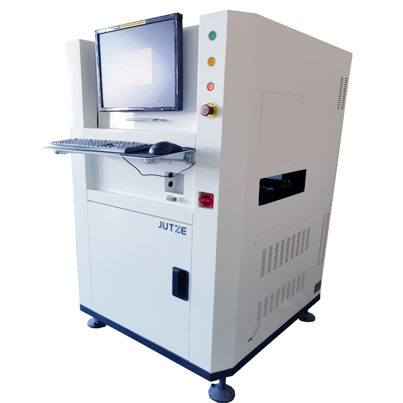
Figure 1: An inline AOI station inspects components and solder joints after placement and reflow. Image: JHIMS product page.
| Item | SPI | AOI |
|---|---|---|
| Position in the line | After the printer, before placement | After placement and/or after reflow |
| What it measures | Paste volume, area, height, offset, shape | Component presence, polarity, alignment, joint appearance |
| Defects it catches | Missing, insufficient or excessive paste; offset; print bridging | Missing or wrong parts; polarity errors; tombstones; lifted leads; post-reflow bridging |
| What it cannot see | Any component or joint defect | Paste volume under a component; hidden joints under BGA or QFN packages |
| What it feeds back to | The printer: cleaning, offset correction, process drift | Placement and reflow process monitoring; rework decisions |
One boundary to state plainly: hidden solder joints under BGA and QFN packages are outside both stations' scope. If hidden joints are your main risk, neither an SPI nor an AOI purchase closes that gap — that is an X-ray decision, and it should be budgeted separately rather than loaded onto an AOI specification.
The audit has four steps. It uses records your line already produces — rework logs, scrap records and functional-test failures — and it classifies each escape by where it originated, not by where it was found.
Step 1 — Collect a representative period. Gather failures over a period that covers your main products and your normal shifts. A single product or a single quiet week will mislead the decision. Keep the period the same for every defect class so the comparison is fair.
Step 2 — Classify by origin, not by discovery point. For each failure, ask: which process step created it? Use five buckets: print origin, placement origin, reflow-solder origin, component or material origin, and unknown. A bridge found at functional test that was caused by excess paste is a print-origin defect, even though it was discovered late.
Step 3 — Assign the earliest station that could have caught it. Print-origin defects go to SPI. Placement and visible post-reflow joint defects go to AOI. Hidden-joint defects go to neither — mark them separately so they do not inflate the case for either station.
Step 4 — Rank by rework stage, not just by count. A defect caught at print costs a bare printed board and a reprint. The same defect caught after reflow costs placed components and rework labour. A defect that escapes to the customer costs the most of all. Weight the ranking by the stage at which each class is caught today, using your own rework routing — not a generic cost ladder from a brochure.
| Defect example | Origin | Earliest catching station | Your count (fill in) |
|---|---|---|---|
| Insufficient paste on fine-pitch pads | SPI | ||
| Print bridging between adjacent pads | SPI | ||
| Missing or wrong component | Placement | AOI | |
| Tombstone or lifted lead | Placement / reflow | AOI | |
| Void under a BGA ball | Reflow / hidden joint | Neither — X-ray scope |
Separately, check print stability itself. If your printer's paste volume, area, height and offset trends are already stable across products and shifts, SPI still adds monitoring value, but it is unlikely to be your first payback. If print drifts with stencil cleaning, paste condition or board support, that drift is exactly what SPI is built to catch early.
Read the row that matches your audit result, not the row that matches your budget cycle. The matrix below is a decision aid, not a measured outcome: it tells you where to look first, and your audit tells you whether the row applies.
| Your audit shows | Buy first | Why |
|---|---|---|
| Print-origin escapes dominate, or print drifts between cleaning cycles | SPI | Stops bad boards before components are committed, and feeds corrections back to the printer |
| Print is stable, but placement and post-reflow joint defects dominate | AOI | Covers the defect classes SPI cannot see, at the point where they become visible |
| High product mix with frequent changeover and varied component types | AOI first, if placement errors lead | One AOI program family covers many component types; confirm programming time per product before ordering |
| A customer or audit requires per-board post-reflow joint evidence | AOI | SPI records paste, not finished joints; only post-reflow inspection evidences the joint |
| You already own one station and its defect class is now controlled | Re-audit, then the other | Do not buy the second station to "complete the set"; buy it when its defect class becomes the top escape |
| Hidden-joint defects dominate | Neither first | Route this risk to an X-ray plan; an AOI purchase will not evidence joints it cannot see |
If SPI is first, specify: true 3D measurement of volume, area, height, offset and shape — not a 2D-only check; SPC trending per joint so drift is visible before it becomes scrap; closed-loop feedback to your printer model, including what the SPI can trigger (for example stencil cleaning or offset data) and which printer protocols it supports; board size and thickness range against your largest panel; and whether bad-board data can be shared with your placer, if your placer accepts it.
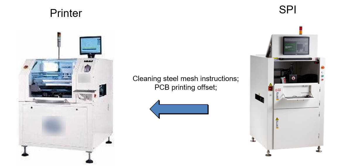
Figure 2: SPI in a closed loop with the printer — the printer (left) and the SPI station (right), with stencil-cleaning and print-offset feedback. Image: JHIMS product page.
If AOI is first, specify: inspection position — post-reflow only, or pre-reflow as well for placement errors; 2D versus 3D capability for lifted leads and coplanarity, where height data matters; programming method and time per new product, which decides whether high-mix production stays practical; and the operator verification workflow, including who reviews flagged boards and how much line time that review takes.
Three mistakes to avoid. First, comparing vendor false-call percentages directly: rates measured on different boards, defect sets and thresholds are not comparable, so ask each vendor to demonstrate on your boards instead. Second, counting only inspection speed and ignoring verification labour — a fast station with a slow review queue still bottlenecks the line. Third, accepting default thresholds without a review routine: thresholds set once at installation drift out of step with your products, so schedule a regular SPC and threshold review from the start.
Run a baseline period covering your main products, then review the station's data on a fixed rhythm — weekly is a practical starting point for most lines. Look for three things: whether the defect class the station was bought for is falling, whether a different class has now become the top escape, and whether thresholds or printer and placement settings need adjustment.
Only then re-run the Section 2 audit. If the second station's defect class is now the top escape, the case for it is made by your own data. If it is not, the money stays better spent on process fixes at the step that is actually failing.
JHIMS offers 3D SPI in two models whose published specifications agree on the core measurement set. The table below uses only specifications that appear on both the jhims.com S460 page and the jhims.net S630 page, so the figures are cross-checked rather than taken from a single listing.
| Specification (both listings) | Value |
|---|---|
| Camera | 5 megapixel, telecentric imaging |
| Resolution | 16 µm (13 µm option) |
| Measurements | Volume, area, height, XY offset, shape |
| Gage R&R | Under 10% |
| Field-of-view speed | 0.45 s per field of view |
| Minimum pad spacing | 150 µm |
| Board thickness range | 0.4–7 mm |
| Component clearance | Top 30 mm / bottom 40 mm |
| Warp compensation | Z-axis dynamic compensation, ±5 mm |
| Data and feedback | SPC analysis, closed-loop printer feedback, bad-board sharing with the placer |
Board size is model-specific, so check it against your largest panel rather than assuming either model fits: the S460 covers up to 460 × 460 mm on jhims.com, and the S630 covers up to 630 × 550 mm on jhims.net. See the JHIMS S460 3D SPI machine on jhims.com and the JHIMS S630 3D SPI machine on jhims.net. For the AOI side, the inline AOI machine listed on jhims.com should be specified the same way: confirm its board-size and resolution limits against your largest, finest-pitch board before ordering, and demonstrate it on your boards rather than relying on brochure performance claims. Background on all three inspection technologies is covered in the earlier JHIMS overview How AOI SPI X-Ray Inspection Is Transforming PCB Quality in 2026.
Limitations, stated plainly: this guide gives you a decision method, not a measured payback figure — payback depends on your defect mix, volumes and rework routing, and no percentage improvement is claimed here. Model-specific figures that appear on only one site listing, and any price or rating figures on product pages, are deliberately not quoted in this article; confirm them with JHIMS before specifying.
Can AOI replace SPI?
No. AOI inspects components and joints after placement. It cannot recover paste-volume information once components cover the deposits.
Can SPI replace AOI?
No. SPI inspects paste before placement. It cannot detect missing, wrong or misaligned components, or post-reflow joint defects.
If the budget covers only one station, which one?
The one whose defect class your audit ranks first. As a rule of thumb only: print-origin dominance points to SPI first, placement and joint dominance with stable printing points to AOI first — and the audit, not the rule of thumb, decides.
Does 3D AOI inspect hidden BGA joints?
No. Optical inspection, 2D or 3D, cannot see through a component body. Hidden joints need X-ray inspection or another appropriate method.
For SPI specifications, board-size confirmation or a demonstration on your boards, contact JHIMS at [email protected].


 Teams
 whatsapp
 telegram
